Car Suspension Diagram: Understanding Your Vehicle’s Key Systems
Maintenance decisions improve dramatically when drivers and technicians can read a car suspension diagram accurately. A detailed schematic shows exactly where each component sits, how it connects to the frame, and what adjacent parts it interacts with under load. A car radiator diagram similarly maps the cooling circuit — from the upper hose to the thermostat housing, reservoir, and return line — which helps diagnose leaks and blockages without guesswork. Together with a review of the types of car suspension in play, a car axle diagram that shows shaft position relative to the differential, and a car relay diagram that traces electrical switching logic, these visual tools give any repair effort a reliable reference baseline. Vehicles that are maintained with diagram-guided accuracy experience fewer repeat failures and lower total repair costs over time.
Reading a Car Suspension Diagram
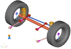
A car suspension diagram typically shows a front or rear corner of the vehicle in exploded view. The frame or subframe anchors at the top, followed by the upper control arm (if present), the spring and shock absorber assembly, the lower control arm, the steering knuckle, and the wheel hub. Every connection point — bushing, ball joint, or bearing — appears labeled with a part number and torque specification in a factory service diagram.
Independent vs. Dependent Suspension
The first thing to identify when reading any suspension schematic is whether the design is independent or dependent. Independent suspension allows each wheel to travel vertically without affecting the wheel on the opposite side. Most modern front suspension systems and many rear suspension systems on passenger cars use independent designs. Dependent suspension — beam axles and solid rear axles — connects both wheels on an axle rigidly. When one wheel hits a bump, the opposite wheel is affected. A car suspension diagram for a solid rear axle looks very different from one showing a multi-link independent rear setup.
Key Components and Their Roles
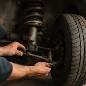
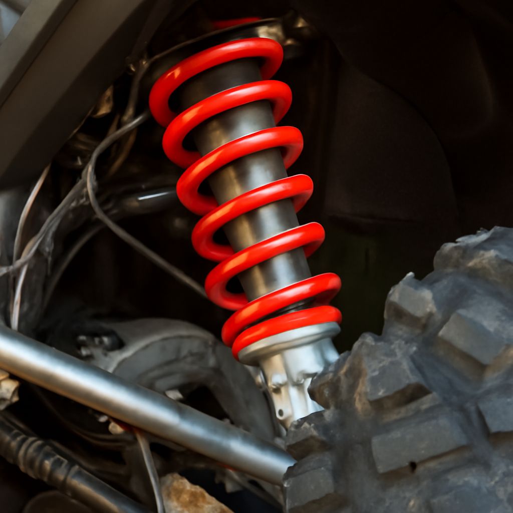
Springs absorb the initial energy of a bump. Shock absorbers (dampers) control how quickly the spring rebounds after compression. Control arms locate the wheel hub relative to the chassis and allow vertical movement. Ball joints form the pivot points between the control arm and steering knuckle. Bushings at every pivot point isolate vibration and provide slight compliance. Identifying worn components using the diagram guides targeted replacement rather than unnecessary part swaps.
Types of Car Suspension Systems
The three most common types of car suspension found on modern passenger vehicles are MacPherson strut, double-wishbone, and multi-link. MacPherson strut is the simplest and most compact — used on most economy and mid-size front-suspension applications. It combines the spring and damper into a single unit that also serves as the upper steering pivot. Double-wishbone suspension uses two control arms per corner for better camber control during cornering, which is why it appears on sports cars and performance SUVs. Multi-link setups with four or five separate links per rear corner offer the most tuning flexibility for ride and handling balance but are the most complex to diagram and service.
Understanding the types of car suspension installed on a specific vehicle informs both diagnostic logic and parts sourcing. A MacPherson strut replacement is a beginner-level task with the right spring compressor; a multi-link rear suspension adjustment requires alignment equipment and precision torque tools.
Related Vehicle Diagrams: Radiator, Axle, and Relay
Suspension diagrams gain context alongside other system schematics. A car radiator diagram maps coolant flow from the engine water jacket through the upper radiator hose, down through the core where heat is exchanged with passing air, through the lower hose, and back to the water pump. Identifying the radiator petcock location on the diagram simplifies coolant drain procedures. The overflow reservoir and its connection to the radiator filler neck also appear — essential for proper coolant level maintenance. Referring to a car radiator diagram before pulling hoses prevents wrong-hose removal and the coolant spill that follows.
Car Axle Diagram Basics
A car axle diagram for a front-wheel-drive vehicle shows the inner CV joint at the differential output flange, the axle shaft, and the outer CV joint at the wheel hub. The outer joint must articulate through a wide angle for steering, making its boot the most likely to crack and lose grease. A car axle diagram for a rear-wheel-drive vehicle shows the driveshaft from the transmission, the rear differential, and the shorter half-shafts to each rear wheel — useful for locating the differential fill and drain plugs before a fluid service.
Car Relay Diagram Overview
A car relay diagram appears in the vehicle’s electrical section of the factory service manual. It shows which relay controls each circuit — fuel pump, cooling fan, horn, starter, and accessory systems — and where each relay is physically located in the fuse box. A car relay diagram saves diagnostic time when a system fails intermittently. Swapping a suspected relay with an identical relay from a non-critical circuit is a fast zero-cost test. If the failing system starts working after the swap, the original relay is confirmed faulty.
Pro tips recap: Always match the suspension diagram to the specific vehicle year and trim level — the same model may use different configurations across production years. Use the car radiator diagram before any cooling work to confirm hose routing. Reference the car axle diagram to locate CV boot positions before any axle inspection, and consult the car relay diagram first when any electrical circuit fails intermittently.